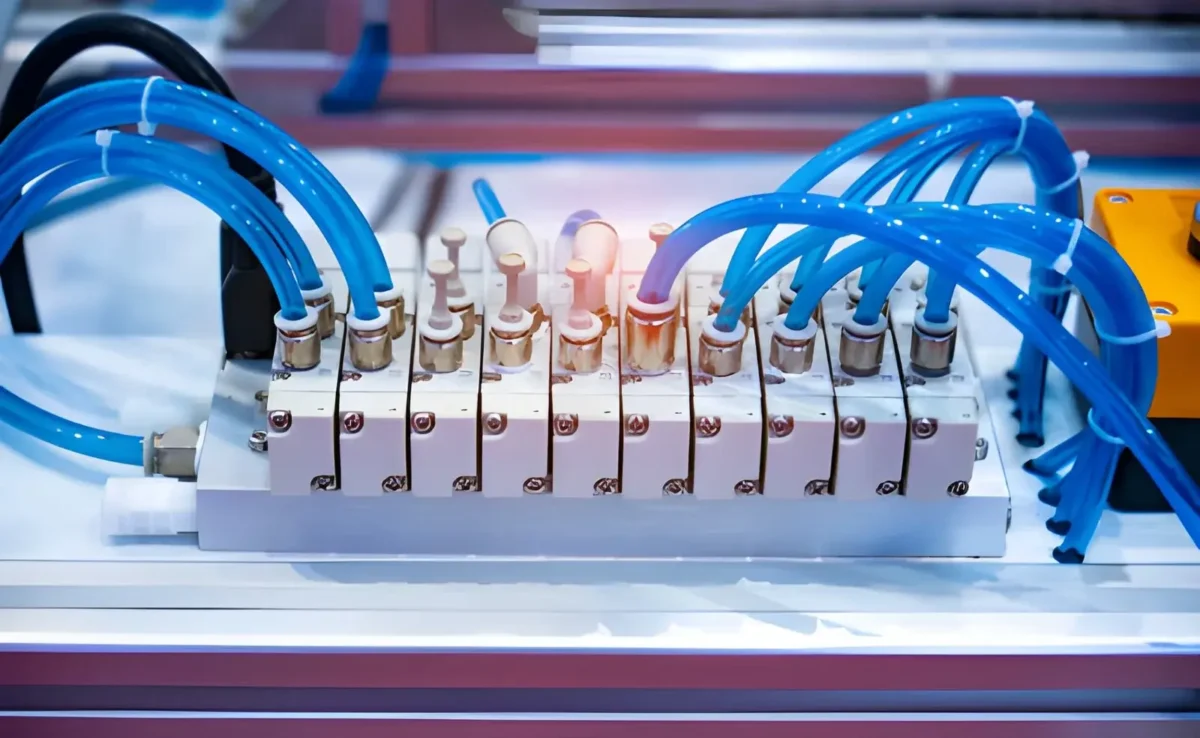

Compressed air can power a lot of movement in a machine, but it needs somewhere to go — and a way to get there at the right time. Pneumatic valves manage that airflow. They can open or shut an air line, send air in a different direction, or change the pressure and flow going to another part of the system.
A pneumatic cylinder is a simple example. To extend the cylinder, the system sends air to one side of the piston. To bring it back, the airflow has to change. The valve handles that switch.
There are several common valve types, each built for a different job:
- Directional control valves — send air along the required path.
- Pressure control valves — keep pressure at the required level or prevent it from getting too high.
- Flow control valves — change the airflow to control how quickly an actuator moves.
- Check valves — let air pass in one direction but block it in the other.
- Quick exhaust valves — let air escape close to the cylinder when a faster response is needed.
Pneumatic valves show up in almost every type of automated equipment: packaging lines, conveyors, assembly machines, material handling systems, production equipment, and pneumatic tools. Their role varies from one machine to another, but the basic purpose is the same — controlling where compressed air goes and what happens when it gets there.
Pneumatic Valves: Types, Functions, and Industrial Applications
Compressed air can make a cylinder move, operate a gripper, or control another part of a machine. But the air needs to be sent to the right place at the right time. That is what pneumatic valves do.
Depending on the design, a valve can:
- start or stop airflow;
- send compressed air in a different direction;
- regulate pressure;
- adjust the amount of air flowing through the system;
- control when and how a pneumatic actuator moves.
For example, a directional valve can send air to one side of a cylinder to extend it and then switch the airflow to retract it. A pressure valve has a different job: it keeps pressure within the required range. Flow control valves, meanwhile, can be used to change how quickly a cylinder moves.
This is why there is no single pneumatic valve that works for every task. When choosing one, you need to look at what the valve needs to do first, then check its port configuration, flow capacity, operating pressure, and actuation method. The working environment matters too, especially when the valve is exposed to dust, moisture, high temperatures, vibration, or aggressive media.
Pneumatic valves are used throughout industrial automation, including packaging lines, assembly equipment, conveyors, material handling systems, manufacturing machinery, and process equipment. In all of these applications, they provide a practical way to control compressed air and turn it into predictable machine movement.
What Is a Pneumatic Valve?
A pneumatic valve is a device that controls compressed air inside a pneumatic system. Depending on its design, it can open or close an air line, send air in a different direction, adjust pressure, or control how much air passes through the system.
You can see this clearly in a pneumatic cylinder. The valve sends compressed air to the cylinder when movement is needed and controls where that air goes. By switching the airflow from one side of the piston to the other, the valve can make the cylinder extend or retract.
A typical pneumatic system includes several components working together:
- Compressor — provides the compressed air.
- Tubing and fittings — carry air through the system.
- Pneumatic valve — controls where and when the air flows.
- Cylinder or rotary actuator — converts air pressure into movement.
- Control system — tells the valve when to operate.
Pneumatic valves can also be operated in different ways. Some are switched manually with a lever or button, while others respond to mechanical contact or pneumatic pressure. In automated machinery, electrically operated solenoid valves are common because they can receive commands directly from a PLC or other control system.
The operating method depends on the machine, but the basic purpose stays the same: control compressed air so the pneumatic system performs the required movement or function.
Main Types of Pneumatic Valves
Pneumatic valves are grouped by the job they perform in an air circuit. Some simply turn airflow on and off, while others change its direction, regulate pressure, or control how quickly air moves.
Directional Control Valves
Directional control valves decide where compressed air goes. They connect and disconnect different flow paths inside the valve, allowing the system to start or stop airflow or change the direction of an actuator.
For example, a directional valve can send air to a cylinder to extend it and then switch the flow so the same cylinder retracts.
These valves are usually described by two numbers. The first shows the number of ports, and the second shows the number of valve positions.
Common configurations include:
- 2/2-way valve — 2 ports and 2 positions. A simple choice for opening or closing an air line.
- 3/2-way valve — 3 ports and 2 positions. Commonly used with single-acting cylinders because it can supply air and then exhaust it.
- 4/2-way valve — 4 ports and 2 positions. Can reverse airflow to control a double-acting actuator.
- 5/2-way valve — 5 ports and 2 positions. Often used with double-acting cylinders, with separate exhaust paths for each side.
- 5/3-way valve — 5 ports and 3 positions. Adds a center position, giving the system another way to manage the actuator when it is not moving.
The right configuration depends mainly on the type of actuator and what you need it to do. A simple on/off air supply may only need a 2/2 valve, while a double-acting cylinder that must extend and retract normally requires a valve capable of switching air between both sides of the piston.
| Valve Type | Typical Function | Common Application |
| 2/2-way | Start/stop airflow | Air supply control |
| 3/2-way | Supply and exhaust | Single-acting cylinder |
| 5/2-way | Reverse airflow | Double-acting cylinder |
| 5/3-way | Multi-position control | Cylinder positioning/control |
Pneumatic Valve Actuation Methods
A pneumatic valve needs a signal or physical action to switch from one position to another. How this happens is called the actuation method. The right option depends on whether the valve needs to work automatically, respond to another pneumatic signal, or be operated directly by a person or machine component.
Solenoid-Operated Valves
Solenoid valves are widely used in automated pneumatic systems. When the solenoid receives an electrical signal, its coil is energized and the valve changes position.
This makes them easy to integrate with:
- PLCs;
- sensors;
- timers;
- industrial control systems.
A PLC can switch the valve at a specific point in a machine cycle, allowing cylinders and other pneumatic actuators to operate automatically. Solenoid valves are therefore common in packaging, assembly, material handling, and other automated equipment.
Pneumatically Actuated Valves
Pneumatically actuated valves use compressed air as the control signal. When pilot pressure reaches the valve, it moves the internal mechanism and changes the airflow path.
They are useful in pneumatic control circuits where:
- an electrical signal is not required;
- one pneumatic component needs to control another;
- remote operation using an air pilot signal is preferred.
Manual Valves
Manual valves are operated directly by a person rather than by an automatic control signal.
Common operating methods include:
- push buttons;
- levers;
- pedals;
- handles.
They are often used for machine setup, manual operations, testing, and maintenance tasks where an operator needs direct control over airflow.
Mechanically Actuated Valves
Mechanically actuated valves switch when a moving machine part makes physical contact with the valve mechanism.
Common designs use:
- rollers;
- plungers;
- levers.
For example, a moving machine component can press a roller valve when it reaches the end of its travel. The valve then switches the airflow and triggers the next step in the sequence.
This makes mechanically actuated valves useful for position detection, end-of-travel control, and simple pneumatic sequences without requiring a separate electrical sensor.
Normally Open vs Normally Closed Pneumatic Valves
Normally Open (NO) and Normally Closed (NC) describe what the valve does when there is no control signal. This is important because it determines what happens to the airflow when power or the actuation signal is lost.
- Normally Closed (NC) — the flow path is closed in its normal state. Air only passes through the valve when it is actuated.
- Normally Open (NO) — the flow path is open in its normal state. Air can pass through until the valve is actuated and closes the path.
For example, if compressed air should only reach an actuator when the machine is running, an NC valve may be the more suitable choice. If airflow needs to remain available during normal operation and stop only when the valve receives a signal, an NO design may make more sense.
The choice should also consider what the machine needs to do if power or a control signal is lost. Depending on the application, the safest state may be to stop airflow, release pressure, or keep a particular air path open.
This is why NO or NC selection should be based on the required fail-safe behavior of the complete pneumatic system, not simply on which configuration is more commonly used.
Common Pneumatic Valve Problems
Pneumatic valves can develop problems because of wear, contamination, incorrect sizing, low pressure, or electrical faults. The symptoms are often similar, so it helps to check both the valve and the surrounding pneumatic circuit before replacing any component.
Common problems include:
- Air leakage — may come from worn seals, loose fittings, damaged tubing, or internal valve wear.
- Contamination — dirt, oil, water, or other particles can enter the valve and interfere with moving parts.
- Blocked exhaust — a restricted exhaust path can slow down cylinder movement or prevent proper pressure release.
- Worn seals — seals can harden, crack, or wear over time, causing internal or external leakage.
- Sticking spool — contamination, corrosion, or lack of proper lubrication can prevent the spool from moving freely.
- Insufficient pilot pressure — a pilot-operated valve may switch slowly or not switch at all if the available pressure is too low.
- Incorrect valve sizing — a valve with insufficient flow capacity can restrict airflow and slow actuator movement.
- Damaged solenoid coil — an overheated or failed coil may prevent an electrically operated valve from switching.
- Electrical connection problems — loose wiring, incorrect voltage, damaged connectors, or control-signal faults can stop the solenoid from operating.
A few basic checks can help narrow down the cause:
| Problem | Possible Cause | What to Check |
| Valve does not switch | Low pilot pressure, damaged coil, electrical fault | Pilot pressure, supply voltage, wiring, coil |
| Cylinder moves slowly | Undersized valve, blocked exhaust, restricted tubing | Valve flow rating, tubing, fittings, exhaust |
| Air leaks from valve | Worn seals, damaged fittings, internal wear | Seals, connections, valve body |
| Valve switches inconsistently | Contamination or sticking spool | Air quality, spool movement, filtration |
| Solenoid does not operate | Failed coil or incorrect voltage | Coil condition, voltage, connector |
| Actuator loses pressure | Leakage or damaged seals | Valve, tubing, fittings, actuator seals |
Not every actuator problem is caused by the valve itself. Air supply, tubing, fittings, cylinders, wiring, and controller settings should also be checked when troubleshooting a pneumatic system.
Also Read
- build-your-global-legal-career-with-llb-in-dubai-llm-in-dubai-study-from-uae/
- how-hiring-a-qualified-plumber-in-philadelphia-resolves-emergency-plumbing-issues/
- /transforming-workspaces-the-ultimate-guide-to-commercial-cleaning-excellence/





Leave a Comment